Nothing about a standby generator matters if it cannot start immediately when utility power fails. The most common cause of start failures is a weak or neglected battery system. While diesel engines can technically be started using pneumatic or hydraulic methods, over 95% of industrial generators today use electric starting—powered by lead-acid batteries and managed by solid-state battery chargers. This article explains battery sizing, charger selection, cable routing, cold-start support, and maintenance best practices for reliable generator starts.
Starting System Components
- Starter Motor: Heavy-duty DC motor (typically 24 V for engines ≥ 6 L, 12 V for smaller sets), engaged to the flywheel via a clutch.
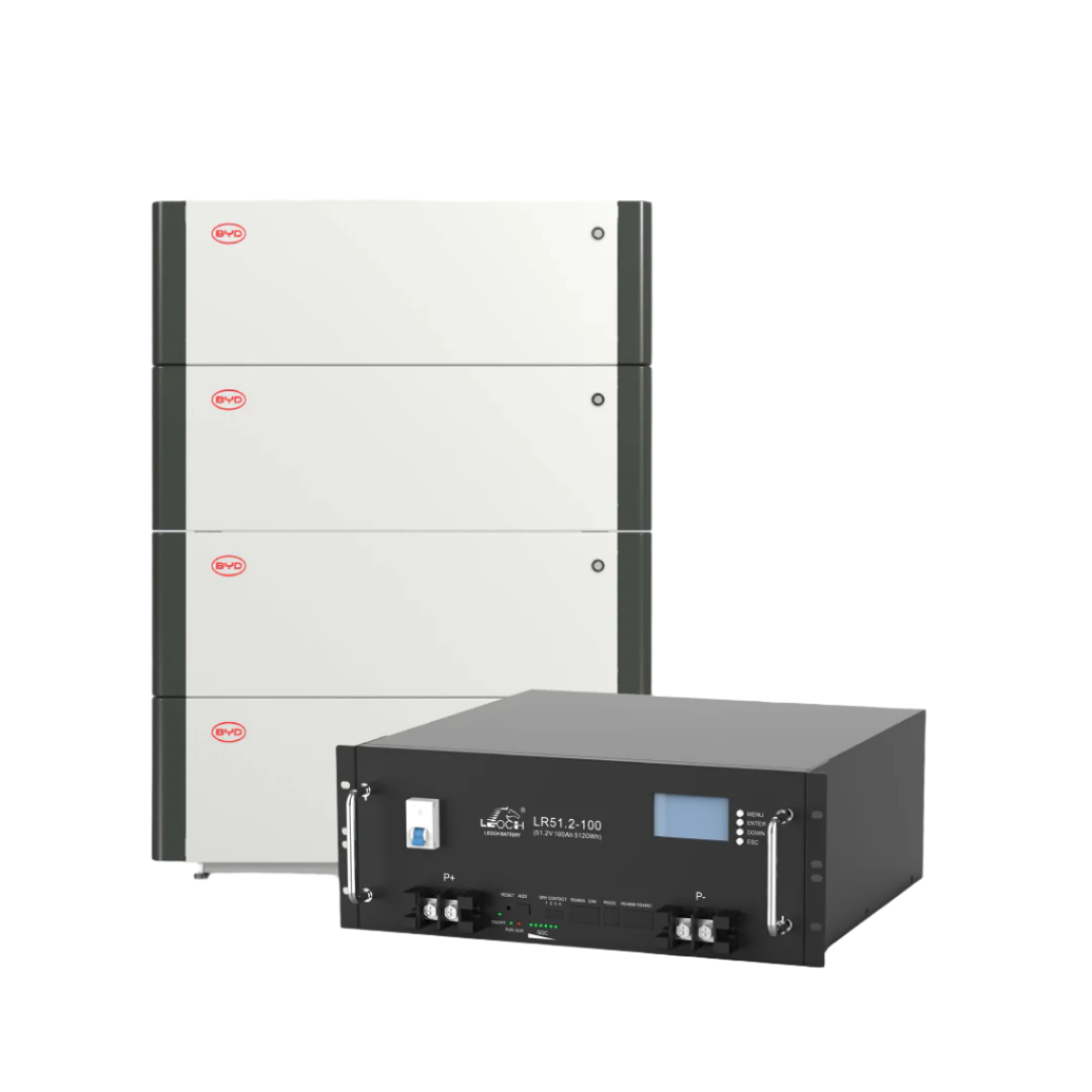
- Batteries: Flooded lead-acid (FLA), absorbed glass mat (AGM), valve-regulated lead-acid (VRLA), or lithium cells wired in series.
- Battery Charger: Microprocessor-controlled unit that maintains float voltage, periodically equalizes charge, and powers auxiliaries.
- Cables & Disconnects: Copper conductors sized for ≤ 3% voltage drop at locked-rotor amps (LRA), with an isolator switch for service.
- Cold-Start Aids: Jacket-water heaters, intake-air heaters, or ether injection for ambient conditions below 10 °C.
Battery Chemistry Options
| Type | CCA per 100 Ah | Maintenance | Service Life |
|---|---|---|---|
| Flooded (FLA) | ~600 A | Monthly electrolyte check | 3–5 years |
| AGM | ~700 A | Sealed; visual only | 5–7 years |
| Pure-lead AGM | ~850 A | Sealed | 8–10 years |
| Lithium (LFP) | ~1 200 A | Requires BMS | 10–15 years |
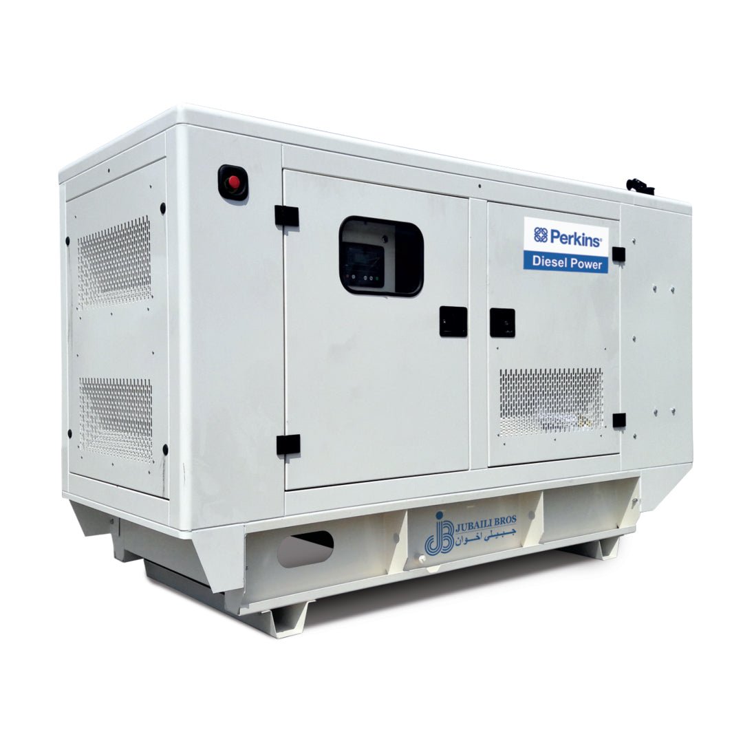
For critical systems, NFPA 110 recommends dual starting battery banks. Many Jubaili Bros generators ≥ 1 MVA are equipped with redundant 2 × 200 Ah AGM banks and dual battery chargers configured in failover mode.
Battery Sizing Formula
To calculate required cold-cranking amps (CCA):
CCA ≥ (Starting current at 0 °C) × (1 + cable drop factor + ageing factor)
Typical starting current = 4.0 A per cm³ engine displacement at 0 °C. Apply a 25% ageing factor for AGM and 40% for FLA. Cable drop factor accounts for voltage losses at the expected cable length.
Cable Sizing and Voltage Drop
Keep voltage drop ≤ 3% (0.72 V on a 24 V system). Minimize distance between battery and starter motor. If over 1 m, increase conductor size to 70 mm² or 95 mm² copper. Use Class 5 flexible cable with crimped, tinned lugs and heat-shrink insulation for corrosion protection.
Battery Chargers
Three-stage smart chargers are recommended:
- Bulk: Constant current to 80% state of charge.
- Absorption: Constant voltage until current tapers.
- Float: 2.25 V/cell (27.0 V for 24 V) at 25 °C.
Apply temperature compensation at −0.03 V/°C/cell to prevent overcharging in hot environments. Jubaili Bros supplies chargers with fail relays connected to DSE controllers for battery fault alarms and remote monitoring.
Cold-Start Aids
- Jacket-Water Heaters: Maintain coolant at 40–50 °C. Thermostat-controlled and monitored for low-temperature alarms.
- Intake Air Heaters: Glow plugs or grid heaters improve starting and reduce white smoke.
- Ether Injection: Used in sub-zero climates; not recommended unless factory-calibrated.
Preventive Maintenance Schedule
| Interval | Task | Target |
|---|---|---|
| Weekly | Visual check for corrosion; check electrolyte (FLA) | No visible corrosion; levels above plates |
| Monthly | Measure float voltage | 27.0 ± 0.2 V (24 V system) |
| Semi-annually | Conductance or impedance test | Bank-to-bank deviation < 20% |
| Annually | Load test at 50% CCA for 15 s | Voltage ≥ 1.75 V/cell |
| Every 3 years | Replace flooded batteries | – |
Troubleshooting Quick Guide
- Starter clicks, no crank: Battery voltage under load < 22 V → replace battery.
- Slow crank, white smoke: Coolant temperature too low → check block heater supply.
- High float voltage > 28 V: Charger overvoltage → replace or recalibrate charger.
- Hot cable lug: Loose or corroded terminal → retighten to 45 N·m and inspect for sulphation.
Redundant Battery and Charger Configuration
High-availability installations use dual battery banks (A & B), each with independent chargers and isolation relays. In setups using a DSE 8610 controller, the fail contacts of both chargers are monitored. If one charger fails, the system automatically switches to the backup bank and issues a fault alarm—ensuring uninterrupted starting capability.
Safety and Environmental Practices
Install batteries in a ventilated cabinet or enclosure. Hydrogen gas released during charging can become explosive above 4% v/v. Include a hydrogen detector if the system is indoors. Provide an acid-resistant tray sized for 110% of the electrolyte volume. Always wear insulated gloves and face protection when servicing flooded batteries.
Conclusion
The starting system is a small component, but it plays a critical role in standby generator reliability. Proper battery chemistry, right-sized conductors, intelligent chargers, and preventive maintenance ensure that your generator starts instantly—even after months of idle standby.
Need help with battery sizing, charger selection, or redundancy planning? Contact Jubaili Bros to schedule an audit or retrofit with batteries rated up to 1,000 CCA per engine.


