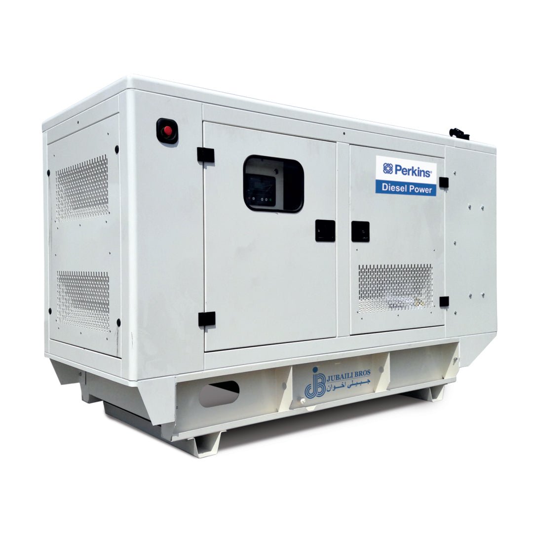
When a diesel generator accepts a sudden load—such as an air-conditioning compressor or a bank of UPS rectifiers—the alternator’s voltage and engine frequency drop momentarily before stabilizing. These transients are known as voltage dip and frequency dip. If they exceed equipment tolerances (typically ±15% for voltage and ±10% for frequency under ISO 8528 G3), contactors may trip, PLCs can reset, and operations are interrupted. The solution lies in coordinated tuning of the alternator’s Automatic Voltage Regulator (AVR) and the engine governor.
What Causes Voltage Dip?
Voltage dip occurs because the AVR cannot instantly increase the field current when additional magnetic flux is needed. Although the AVR reacts within milliseconds, system inertia from the exciter and rectifier bridge causes a short lag, leading to a brief voltage drop.
Why Frequency Dip Happens
Frequency is directly tied to engine RPM. When a block load is applied, torque demand increases suddenly. Until the governor adds fuel to compensate, the engine slows down, causing a temporary drop in frequency. Electronic governors respond in 150–250 ms, while mechanical types take 300–500 ms.
Key AVR Parameters
- Voltage set-point: Target output voltage (e.g., 400 V at 50 Hz).
- Stability / gain: Controls voltage recovery speed; too much gain causes oscillation.
- Under-frequency compensation (UFRO): Limits excitation when RPM drops, avoiding over-fluxing during recovery.
- Excitation ceiling: Defines the maximum field current. Systems like PMG or AREP raise this ceiling to handle larger loads.
Governor Tuning Parameters
- Gain (P): Governs proportional response to speed changes.
- Integral (I): Eliminates residual error; excessive values cause hunting.
- Derivative (D): Dampens overshoot, although not commonly used in genset control.
- Droop: Defines the speed vs. load curve. Typical values are 3–5% for standalone, and 0% for parallel operation.
Transient Performance Standards
| Class | Voltage Dip | Voltage Recovery | Frequency Dip | Frequency Recovery |
|---|---|---|---|---|
| ISO 8528 G3 | ≤ –15% | < 3 seconds | ≤ –10% | < 5 seconds |
| Data Centre Tier III | ≤ –15% | < 1.5 seconds | ≤ –10% | < 3 seconds |
All Jubaili Bros generators are tested to meet G3 performance as a baseline. For hospitals and Tier III data centres, PMG alternators and electronic governors help meet tighter response times.
Step-by-Step Tuning Procedure
- Warm up: Run generator to operating temperature without load.
- Initial governor setup: Set droop to 4% for standalone or 0% for parallel. Adjust gain until light oscillation appears, then back off 10%.
- Apply 30% block load: Record voltage and frequency dip and recovery times.
- Increase AVR gain: Adjust in small increments until voltage overshoot remains below 5%.
- Repeat at 60% and 80% loads: Ensure results remain within performance limits.
- Enable UFRO: Set slope to reduce excitation below 48 Hz to avoid over-fluxing.
- Lock settings: Seal potentiometers and password-protect digital controls.
Worked Example
A 500 kVA set with a PMG-excited TAL-A48 alternator experienced –18% voltage dip and 4 seconds of recovery time during a 300 kW load step. After tuning:
- AVR gain increased from 50% to 65%
- Governor gain increased, and integral setting lowered
Final results: –13% voltage dip and 1.9 seconds recovery; –7% frequency dip and 2.5 seconds recovery—well within G3 and data centre thresholds.
Common Pitfalls
- Over-tuning AVR: Excess gain causes high-frequency voltage oscillations.
- Ignoring power factor: Low-PF loads demand high excitation. Consider upgrading to AREP+ or larger alternators if needed.
- Disabling UFRO: Without it, the AVR may over-flux the alternator, risking overheating and poor recovery.
Integration with Digital Controllers
Controllers like the Deep Sea DSE 7320 and 8610 support auto-tuning of PID settings and include real-time waveform capture for voltage and frequency, greatly simplifying the tuning process.
Maintenance Checks
- Clean AVR heat sinks to avoid thermal derating.
- Check mechanical governor linkages or calibrate electronic actuators every 1 000 hours.
- Repeat transient response tests annually or after any significant change in connected loads.
Conclusion
The coordination between voltage regulation and engine speed control is critical to generator performance. A poorly tuned system risks downtime and equipment damage, while a well-tuned AVR and governor ensure compliance with industry standards and uninterrupted power delivery.
Need help tuning your generator? Contact Jubaili Bros—our field service experts carry load banks and digital scopes for on-site performance optimization.


